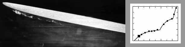
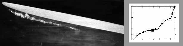
The above graph illustrates the results of a multidimensional test on a 650-MW Francis unit. It shows, in grey scale, the cavitation intensity as acquired by the sensor on guide vane 13 within a time interval covering the passage of four guide vanes. The notation 13/2, 11/3, etc. follows a v/b-scheme presenting the cavitation components caused on runner blade b behind guide vane v. Due to the indivisibility of the numbers of guide vanes and runner blades, 32:13, and the fast reaction of the sensors and electronics, traces of cavitation stemming from all the active v/b-combinations are revealed and, as shown, the load-dependence of the related cavitation intensity is assessed. The three straight lines drawn above the 13/4-trace present the three groups of cavitation mechanisms acting in different load intervals in this particular turbine. Thus, here, there are up to 3×32×13 cavitation processes, which prove to be independent and thus their intensities assessed vibro-acoustically can be combined as additive. This is used in the three basic forms of the turbine cavitation characteristics assessed by the multidimensional method:
• I(Ο) mean global cavitation intensity;
• I(Ο,Θ) circumferential spatial distribution of the mean local cavitation intensity;
• I(Ο,Θ,Φ) time dependent quasi-instantaneous local circumferential spatial distribution, where:
Ο stands for a set of quantities which specify the operation,
Θ is the spatial variable, and
Φ is the runner´s instantaneous angular position which represents the time variable.
Both Θ and Φ are defined between 0° and 360°; Θ takes only the values corresponding to the guide-vane locations.
In addition to the cavitation-intensity functions as defined above, which are derived by means of the sensors on the guide vanes, the following two functions are derived using the sensor on the turbine shaft:
• J(Ο) mean global cavitation intensity, and
• J(Ο,Φ) time dependent quasi-instantaneous global cavitation intensity.
J(Ο) is related to I(Ο), but can differ in typical values and in the dependence on Ο. J(Ο,Φ) is related to the sum of I(Ο,Θ,Φ) over Θ.
The above cavitation descriptions are obtained by the multidimensional analysis/synthesis procedure in which all cavitation segments are equally taken into account. This guarantees the unbiased assessment of all of them. Rather popular simple cavitation assessment methods are not satisfactory. If they are based on one or only a few sensors, they may overestimate some cavitation segments and underestimate others (see "Spatial and temporal..." above) and thus deliver erroneous global assessments. If the sensors are not suitably selected and/or the signal processing in them is not well organised, they cannot deliver time-resolved assessments such as I(Ο,Θ,Φ).
 Korto Cavitation Services